


DH-5860 BGA Rework Station
1.Model: DH-5860 2.Touch screen control: Yes 3.3 independent heating zones: Yes 4.Micro Air Flow Adjust: For top head
Beskrivelse
DH-5860 BGA Rework Station
1.Application of DH-5860 BGA Rework Station
Motherboard of computer, smart phone, laptop, MacBook logic board,digital camera ,air conditioner, TV and
other electronic equipments from medical industry, communication industry, automobile industry, etc.
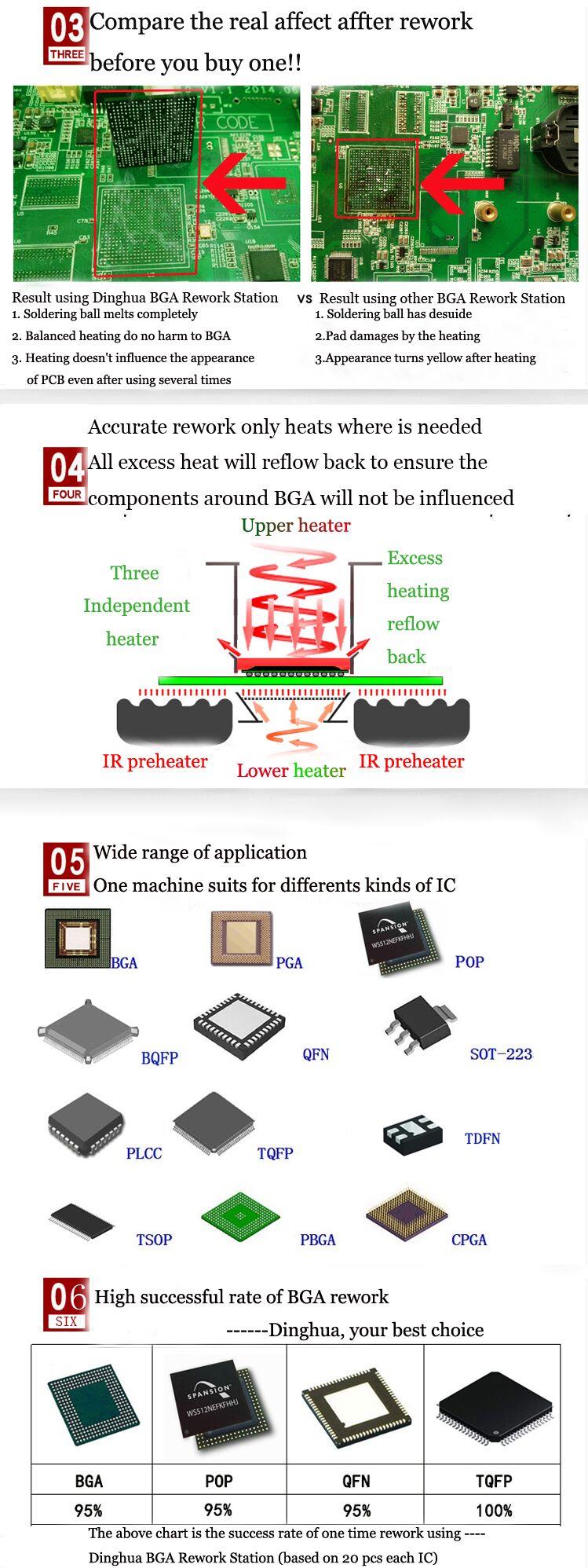
Suitable for different kind of chips: BGA,PGA,POP,BQFP,QFN,SOT223,PLCC,TQFP,TDFN,TSOP, PBGA,CPGA,
LED chip.
2.Product Features of DH-5860 BGA Rework Station

• High success rate of repairing chips.
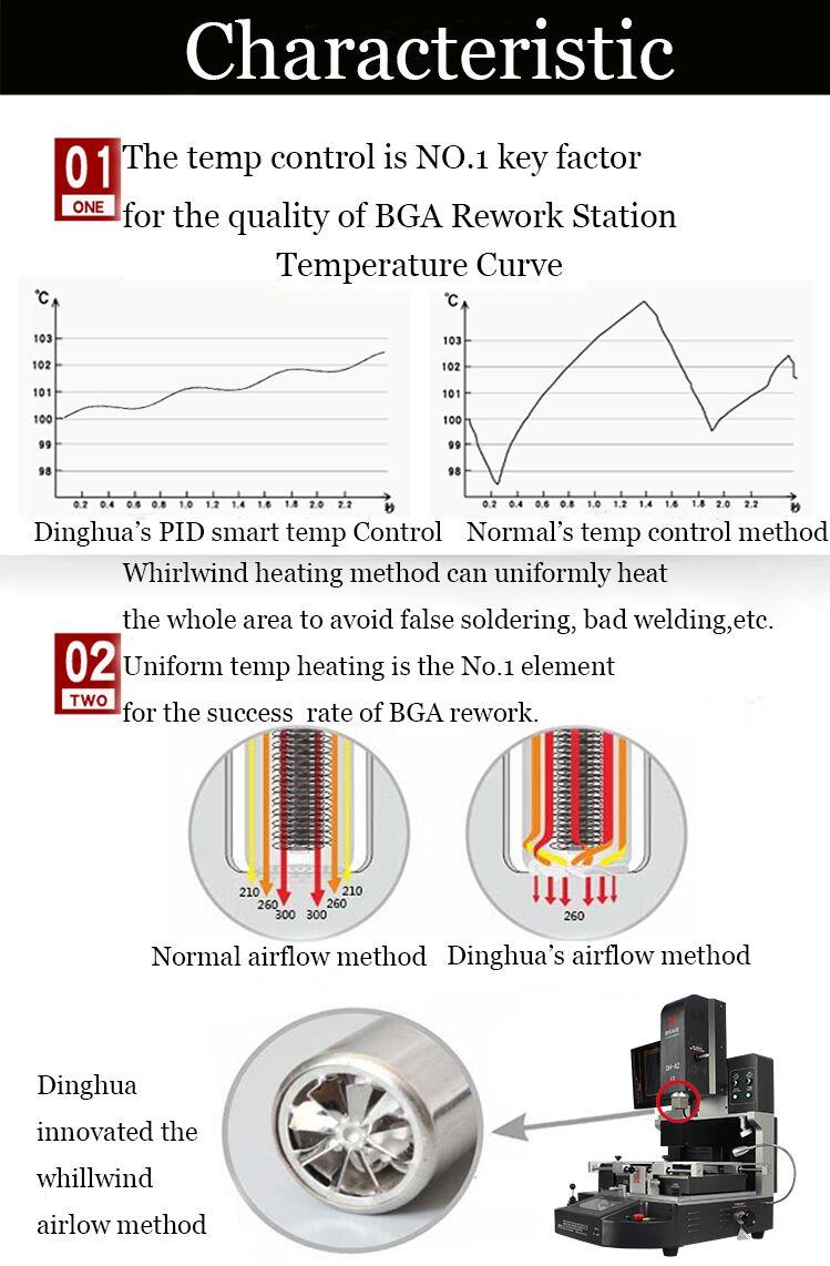
(1)Precise temperature control.
(2)Target chip can be soldered or desoldered while no other components on PCB are damaged.No false welding
or fake welding.
(3)Three independent heating areas increase temperature gradually.
(4)No damage to chip and PCB.
• Simple operation
Humanized design makes the machine easy to operate. Normally a worker can learn to use it in 10 minutes. No
special professional experiences or skills is needed, which is time- and energy-saving for your company..
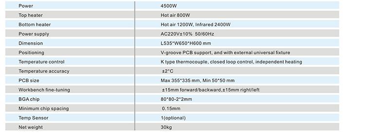
3.Specification of DH-5860 BGA Rework Station
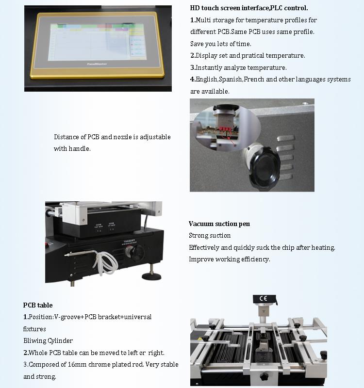
4.Details of DH-5860 BGA Rework Station

5.Why Choose Our DH-5860 BGA Rework Station?
6.Certificate of DH-5860 BGA Rework Station
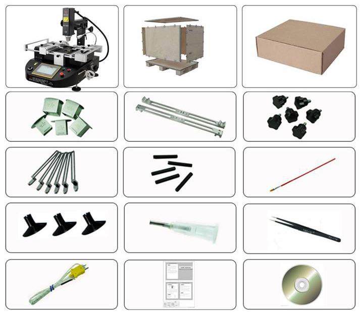
7.Packing & Shipment of DH-5860 BGA Rework Station
8.Related knowledges of DH-5860 BGA Rework Station
Preheating - the premise of successful rework
It is true that long-term processing of PCBs at high temperatures (315-426 ° C) poses many potential problems. Thermal damage, such as
pad and lead warpage, substrate delamination, white spots or blistering, discoloration. Plate warping and burning usually cause the inspector
to pay attention. However, precisely because it does not "burn out the board" does not mean that "the board is not damaged." The "invisible"
damage to the PCB from high temperatures is even more serious than the problems listed above. For decades, numerous trials have repeatedly
demonstrated that PCBs and their components can be “passed” after rework and test, with a higher decay rate than normal PCB boards. The
"invisible" problem of such internal warping of the substrate and attenuation of its circuit components comes from the different expansion coefficients
of different materials. Obviously, these problems are not self-exposed, even undetected at the beginning of the circuit test, but still lurking in the PCB
assembly.
Although it looks good after "repair", it is like a common saying: "The operation is successful, but the patient is unfortunately dying." The cause of the huge
thermal stress is that when the PCB assembly at normal temperature (21 °C) suddenly contacts the soldering iron with a heat source of about 370 ° C, the
soldering tool or the hot air head for local heating, the temperature difference of the circuit board and its components is about 349 ° C. Change, produce
the phenomenon of "popcorn".
The phenomenon of "popcorn" refers to the phenomenon that moisture existing in an integrated circuit or SMD inside the device is rapidly heated during the
repair process, causing the moisture to swell and micro-burst or crack. Therefore, the semiconductor industry and circuit board manufacturing industry require
production personnel to minimize the warm-up time and quickly rise to the reflow temperature before reflow. In fact, the PCB component reflow process already
includes a preheating phase before reflow. Regardless of whether the PCB assembly plant uses wave soldering, infrared vapor phase or convection reflow soldering,
each method is generally preheated or heat treated, and the temperature is generally 140-160 °C. Many problems in rework can be solved with a simple short-term
preheating PCB before reflow soldering. This has been a success in the reflow process for several years. Therefore, the benefits of preheating the PCB assembly prior
to reflow are manifold.
Since the preheating of the plate reduces the reflow temperature, wave soldering, IR/vapor phase welding, and convection reflow soldering can all be performed at
about 260 °C.
The benefits of preheating are multifaceted and comprehensive
First, preheating or "insulation" components prior to initiating reflow helps to activate the flux, removing oxides and surface films from the surface of the metal to be
welded, as well as volatiles from the flux itself. Accordingly, such cleaning of the activated flux just prior to reflow enhances the wetting effect. Preheating heats the
entire assembly to a temperature below the melting point of the solder and reflow. This greatly reduces the risk of thermal shock to the substrate and its components.
Otherwise rapid heating will increase the temperature gradient within the assembly and create a thermal shock. The large temperature gradients created within the
assembly will create thermo-mechanical stresses that cause these low thermal expansion materials to embrittle, causing cracking and damage. SMT chip resistors and
capacitors are particularly susceptible to thermal shock.
In addition, if the entire assembly is preheated, the reflow temperature can be reduced and the reflow time can be shortened. If there is no preheating, the only way is
to increase the reflow temperature further, or to extend the reflow time. Whichever method is not suitable, it should be avoided.
Reduced repairs make boards more reliable
As a reference for the soldering temperature, the soldering method is different, and the soldering temperature is different. For example, most of the wave soldering
temperature is about 240-260 ° C, the vapor phase soldering temperature is about 215 ° C, and the reflow soldering temperature is about 230 ° C. Correctly speaking,
the rework temperature is not higher than the reflow temperature. Although the temperature is close, it is never possible to reach the same temperature. This is because
all rework processes only require heating of a local component, and reflow requires heating of the entire PCB assembly, whether it is wave soldering IR or vapor phase
reflow soldering.
Another factor limiting the reflow temperature in rework is the requirement of the industry standard that the temperature of the components around the rework point
must never exceed 170 °C. Therefore, the reflow temperature during rework should be compatible with the size of the PCB assembly itself and the size of the component
to be reflowed. Since it is essentially a partial rework of the PCB, the rework process limits the maintenance temperature of the PCB. The heating range of the localized
rework is higher than the temperature in the production process to offset the heat absorption of the entire board assembly.
In this sense, there is still no sufficient reason to indicate that the rework temperature of the entire board cannot be higher than the reflow temperature in the production
process, thus approaching the target temperature recommended by the semiconductor manufacturer.


